

Controlled load transfer. Reliable movement. Long-term structural performance.
Bridge bearings form the critical interface between a structure’s superstructure and substructure. They are engineered to safely transmit vertical and horizontal forces while allowing the controlled translations and rotations created by temperature change, traffic, braking, wind, construction tolerances and structural deformation.
Ultraswage’s bridge bearing division brings together elastomer technology, rubber-to-metal bonding, precision steel components and documented quality control to support road, rail, metro, flyover, viaduct and structural applications.
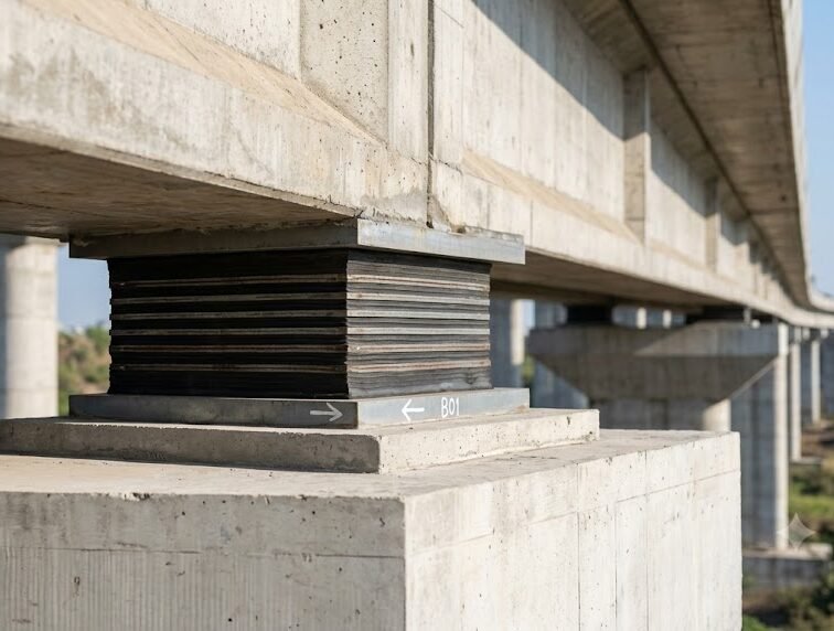
A small component controlling major structural actions
A bridge deck is never completely static. Loads change, spans expand and contract, girders rotate at their supports, and horizontal actions must be safely distributed. The bearing system provides a controlled interface so these actions can occur without introducing unintended restraint into the structure.
Transfer Vertical Loads
Carry reactions from the deck or girder and distribute them into piers, abutments or supporting structural members.
Accommodate Translation
Permit controlled longitudinal and/or transverse displacement caused by thermal movement and structural deformation.
Allow Rotation
Accommodate end rotation of girders and angular movement of the superstructure without damaging the support zone.
Transfer Horizontal Forces
Where required, resist or guide horizontal forces from braking, wind, traffic, seismic effects and other actions.
Define Structural Restraint
Fixed, guided and free-sliding arrangements allow the designer to control how loads and movements are distributed throughout the bridge.
Protect the Structure
Correctly selected and installed bearings reduce local stress concentrations and enable predictable structural behaviour at support locations.
Bridge bearing systems for different load, movement and rotation requirements
No single bearing type is optimum for every structure. Bearing selection depends on the required load transfer, direction and magnitude of movement, rotation, available installation envelope, environmental conditions, inspection requirements and the governing project specification.
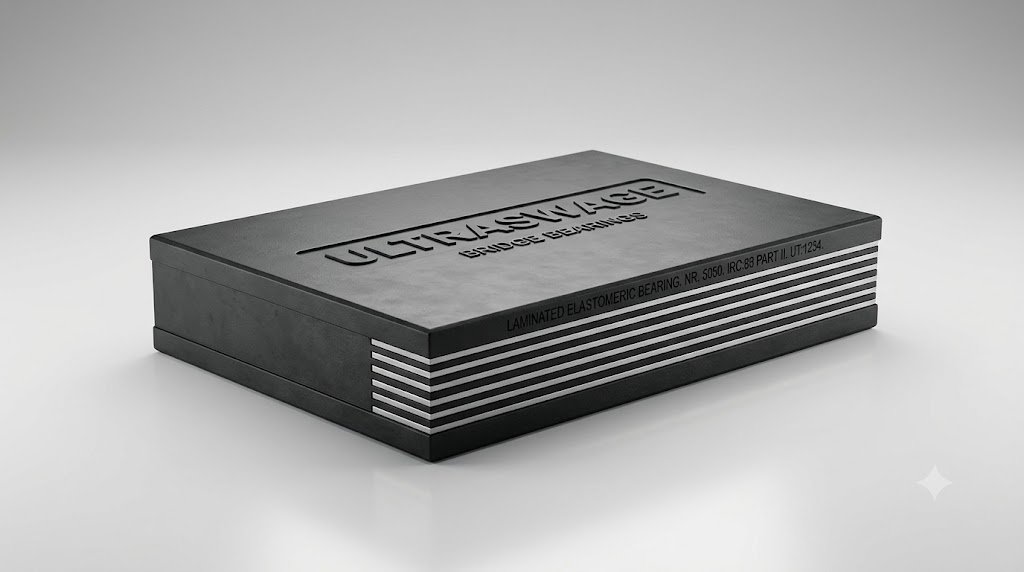
Laminated Elastomeric Bearings
Alternating layers of elastomer and internal steel reinforcement are bonded together during vulcanisation. The steel laminates restrain lateral expansion under compression, giving the bearing high vertical stiffness while retaining the flexibility required for shear movement and rotation.
- Rectangular, square or circular configurations as required by project design.
- Natural rubber (NR) or chloroprene rubber (CR) systems depending on specification.
- Movement accommodated primarily through controlled shear deformation of the elastomer.
- Suitable for many road, rail, flyover and viaduct applications.

PTFE Sliding Elastomeric Bearings
A laminated elastomeric bearing is combined with a low-friction sliding interface. The elastomeric element supports load and accommodates rotation, while the sliding pair allows greater horizontal translation than would normally be provided by elastomer shear alone.
- Low-friction PTFE sliding surface working against a suitable stainless-steel mating surface.
- Used where horizontal movement demand is significant.
- Can be integrated with guide or restraint arrangements depending on structural requirements.
- Sliding surfaces require protection from contamination and installation damage.
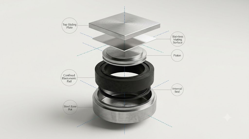
POT / POT-PTFE Bearings
POT bearings use a confined elastomeric pad inside a machined steel pot. Under vertical compression the confined elastomer behaves as a nearly incompressible medium, while deformation of the pad permits rotation of the piston. Sliding elements can be incorporated to provide horizontal movement.
- Available in fixed, guided-sliding and free-sliding functional arrangements.
- Well suited to high vertical reactions where a compact structural bearing is required.
- Steel components can incorporate anchor plates, guide systems and project-specific connection details.
- Corrosion protection and sliding-interface specification are selected for the project environment.
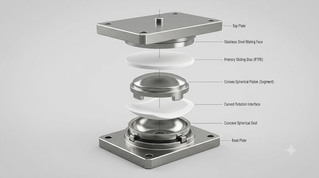
Spherical Bearings
Spherical bearings accommodate rotation by means of matching curved bearing surfaces. A spherical segment transmits vertical load while allowing low-resistance rotation; an additional horizontal sliding plane can provide longitudinal and/or transverse movement.
- Fixed, guided-sliding and free-sliding configurations.
- Suitable for demanding combinations of vertical load, displacement and rotation.
- Can be engineered for restricted installation envelopes and complex structural interfaces.
- Sliding and mating materials are selected to the governing standard and project specification.
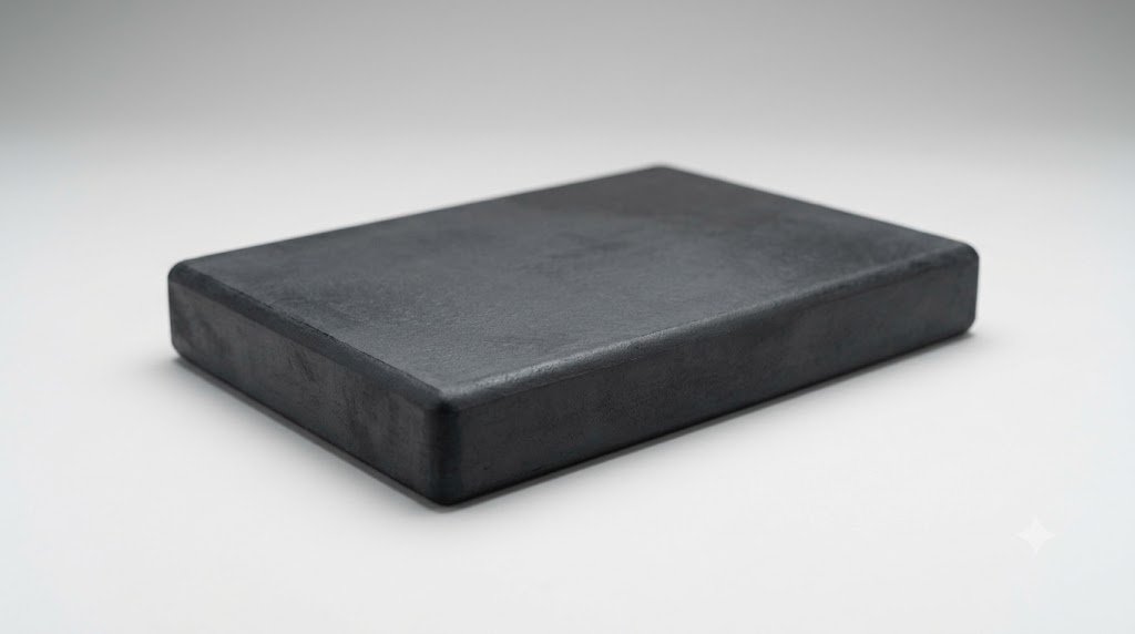
Plain & Strip Elastomeric Pads
Plain elastomeric pads are solid blocks of vulcanised elastomer without internal steel laminates. They provide a simple resilient interface where the structural design permits the required compression, rotation and shear deformation.
- Rectangular, square and strip forms.
- Used for suitable bridge, building and structural-support details.
- Material and dimensions are governed by project design and applicable standards.
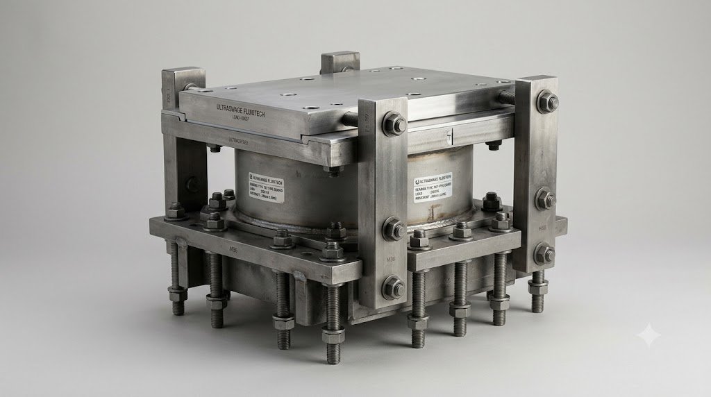
Guide, Restraint & Special Bearings
Structural layouts can require dedicated components to transfer large horizontal forces, restrict movement in a defined direction, resist special actions or interface with replacement and rehabilitation works.
- Guided arrangements for movement along one structural axis.
- Restraint systems for horizontal force transfer where specified.
- Project-specific anchorage, sole plates and connection hardware.
- Special solutions developed against approved engineering requirements.
Fixed, guided or free: the bearing arrangement controls the movement path
Modern structural-bearing systems are commonly arranged according to how they allow or restrain horizontal movement. The correct combination across the structure directs thermal movement and horizontal forces to the intended support locations.
Fixed Bearing
Transfers vertical load and horizontal forces in both principal directions while allowing the rotation for which the bearing is designed.
Guided-Sliding Bearing
Allows displacement in one horizontal direction while transferring horizontal force in the perpendicular direction, together with vertical load and rotation.
Free-Sliding Bearing
Permits horizontal displacement in both plan directions while carrying vertical load and accommodating rotation, with minimal intended horizontal restraint.
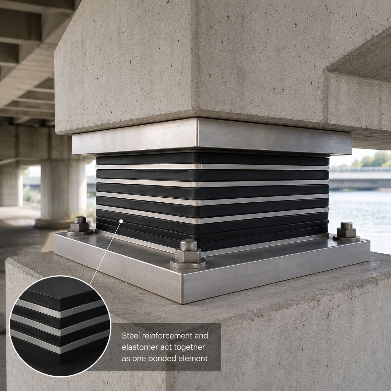
Steel reinforcement and elastomer act together as one bonded element
In a laminated elastomeric bearing, the elastomer provides flexibility while the internal steel plates restrain bulging under compression. Because the reinforcement is fully embedded and bonded during vulcanisation, the bearing behaves as a composite element rather than a stack of loose plates.
Protects embedded reinforcement and forms the external bearing surface.
Provide controlled shear flexibility and rotational compliance.
Restrict lateral expansion and increase compressive stiffness.
Rubber-to-metal adhesion is established during the controlled manufacturing process.
Fixed, guided or free: the bearing arrangement controls the movement path
Modern structural-bearing systems are commonly arranged according to how they allow or restrain horizontal movement. The correct combination across the structure directs thermal movement and horizontal forces to the intended support locations.
| Component | Typical Material / System | Engineering Function |
|---|---|---|
| Elastomer | Natural rubber (NR) or chloroprene rubber (CR), as specified | Provides resilience, shear flexibility, rotation capability and environmental resistance appropriate to the application. |
| Internal reinforcement | Steel laminates / reinforcement plates | Restrains lateral expansion of elastomer under compression and increases vertical stiffness. |
| Structural steel parts | Machined or fabricated steel components to project specification | Transfers load through pots, pistons, base plates, top plates, guide bars, anchor plates and connection hardware. |
| Sliding material | PTFE or other approved structural sliding material | Provides a low-friction sliding interface for controlled translational movement. |
| Mating surface | Suitable stainless-steel sliding surface or approved mating material | Provides the smooth counterface required by the sliding element. |
| Bonding system | Controlled rubber-to-metal primer / adhesive system | Creates durable adhesion between elastomer and metallic reinforcement/components. |
| Corrosion protection | Coating / plating / paint system according to environment and specification | Protects exposed steel surfaces through storage, installation and service. |

From compound preparation to final inspection, every stage affects bearing performance.
Structural bearings operate under sustained compression while repeatedly accommodating movement and rotation. Consistency of compound properties, reinforcement preparation, bond integrity, moulding, machining, assembly and final inspection therefore matters as much as the nominal external dimensions.
Material Control
Bond Integrity
Dimensional Control
Documented QA
A controlled process from raw materials to dispatch
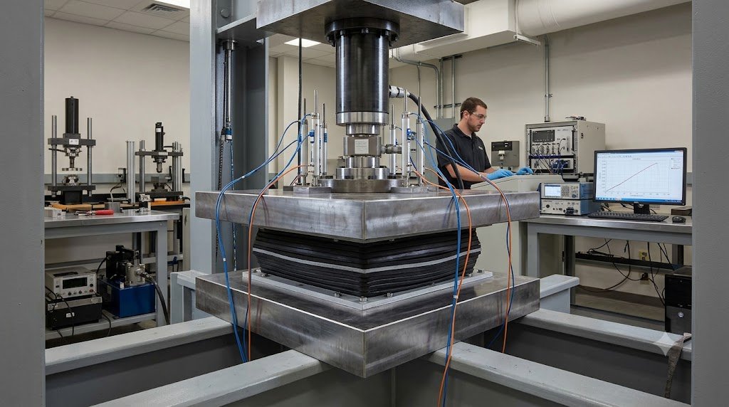
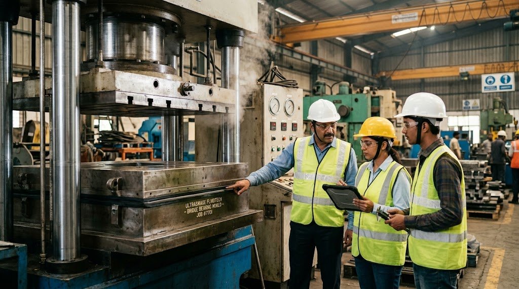
The website should show Ultraswage’s actual manufacturing photographs in this section. The flow below is the intended technical story; the developer should replace generic illustrations with factory images as each operation is confirmed.
Elastomer Preparation
Controlled formulation, mixing, batch identification and process-property checks for the specified bearing compound.
Reinforcement Preparation
Cutting/machining, deburring, cleaning and surface preparation of internal laminates and structural components.
Bonding Preparation
Controlled surface condition and application of compatible bonding systems before mould lay-up.
Lay-up & Vulcanisation
Accurate layer positioning followed by controlled moulding pressure, temperature and cure cycle.
Steel Component Machining
Precision machining and fabrication of POT, spherical, guide, base, top and anchorage components where applicable.
Bearing Assembly
Assembly of elastomeric, sliding and steel components with orientation and fit-up checks.
Final Inspection & Testing
Visual, dimensional, material and complete-bearing checks as required by the approved QAP and governing specification.
Marking & Dispatch
Bearing identification, movement/orientation marks, test documentation, protection and project-wise packing.
Verification at material, component and complete-bearing level
Inspection requirements vary by bearing type and project. Ultraswage’s quality plan should define the applicable tests, sampling, witness points, acceptance criteria and documentation before production.
Visual & Dimensional Inspection
Elastomer Properties
Shear Behaviour
Compression Behaviour
Bond / Adhesion
Sliding / Movement
Load / Proof Testing
Material Traceability
Linkage of elastomer batches, steel records, sliding materials and inspection reports to bearing marks.
Designed and manufactured against the applicable project requirements
Bridge bearings are project-engineered products. The governing code, authority specification, approved drawing and inspection plan define the final design, materials, tests, tolerances and documentation. Applicable references may include:
IRC:83 Series
Applicable parts of IRC:83 for elastomeric, POT/plane-sliding and spherical/cylindrical bridge bearing systems, together with current amendments and project requirements.
RDSO / Indian Railways
Applicable current RDSO specifications, STRs, approved drawings and Railway project requirements for bridge-bearing applications.
MoRTH Specifications
Applicable requirements of the current project edition of the Ministry of Road Transport & Highways specifications and contract documents.
EN 1337
European structural-bearing standard series for project applications where EN requirements are specified.
AASHTO / ASTM
Applicable AASHTO and ASTM requirements for projects designed and procured to North American specifications.
Consultant / Client Specifications
Client drawings, technical specifications, inspection plans and approved deviations take precedence where project requirements are more specific.
Compliance and approval statements must only be published for standards, product ranges and authority approvals actually held or verified by Ultraswage at the time of supply.
Structural support systems for transport and infrastructure projects
- Highway Bridges: Elastomeric and structural bearing systems for concrete, composite and steel bridge superstructures.
- Railway Bridges & ROBs: Bearing solutions engineered to the applicable Railway/RDSO/project requirements.
- Flyovers & Interchanges: Support arrangements for urban flyovers, grade separators and elevated road structures.
- Metro & Viaducts: Bearings for repetitive elevated-span applications with controlled movement and rotation requirements.
- Buildings & Industrial Structures: Structural-support applications requiring controlled load transfer, displacement or rotation.
- Replacement & Rehabilitation: Project-specific bearing replacement solutions developed around existing structural interfaces and approved installation methodology.
Made around the structure — not the other way around
Bearings can be configured around the project’s required load path, permitted movement, rotation, support geometry, installation space and connection details. Depending on the bearing type, project-specific features may include anchor plates, sole plates, guide bars, restraint elements, sliding plates, movement indicators, temporary transport restraints and orientation markings.
Final manufacturing is released against approved drawings and the agreed inspection and test plan, enabling each bearing position to be identified and matched to the bridge bearing schedule.

Engineering documentation that follows the bearing
Infrastructure customers, consultants and inspection agencies require more than a finished component. The supply package can be structured to provide traceability from approved drawing and incoming materials through manufacture, testing, final inspection and dispatch.
Approved Drawings
Quality Plan / ITP
Material Records
Test Certificates
Inspection Release
Bearing Identification
Packing Records
Installation Information
Correct installation preserves the movement the bearing was designed to provide
Even a correctly manufactured bearing can perform poorly if it is installed on an unsuitable seating surface, misoriented, contaminated, damaged or restrained unintentionally. Installation therefore forms part of the complete bearing system.

Bridge bearing fundamentals
Why are steel plates used inside laminated elastomeric bearings?
What is the difference between elastomeric and sliding elastomeric bearings?
What is the difference between fixed, guided and free bearings?
Why are POT bearings used?
When are spherical bearings considered?
Are bridge bearings maintenance-free?
Engineered structural support solutions from Ultraswage.
For bridge bearings, replacement bearings, project-specific drawings and technical requirements, contact the Ultraswage team with the project specification or bearing schedule.